Forward
-------
Here at Engineered Audio, we use a variety of test equipment. We have several O’scopes (Tek TDS340A & Tek 2232), spectrum analyzers (Tek 2794 & HP 3561A), a nice Vector Network Analyzer (HP8753D), a pen plotter (7475A), and various other counters, DMM’s, and power supplies (Tektronix PS5000 series). And the 1 thing they all have in common is a GPIB/HPIB interface.
So, in the not-too-distant past, it was a cumbersome process to take measurements and “plot” the output from the test equipment. First we would send the output to the pen plotter, take that hard plot and scan it into the computer, and then email/archive/print the resulting scanned PDF file.
In a word - Yuck.
Over the past year, we have been playing with a National Instruments Enet-GPIB converter, and while this works great for controlling the various devices (from a Macintosh I might add), it was still cumbersome for printing. What finally made the whole process bearable was finding the Tektronix AD007 GPIB-Ethernet interface.
The magic to the AD007 is that it can do simple print redirection and redirect the GPIB data to an LPD print server. Lucky for us, we have several Mac OS X servers that can (and do) act as print servers.
I’ve asked Bill to write up a small article on how this all came together recently.
--------
Extending OS X's print services to include better HPGL support
and PCL support.
By Bill Siever
Motivation
----------
The goal is to extend Mac OS X's print server (CUPS), so it can
translate either a HPGL or a PCL file to a printable format
(postscript or PDF). Specifically we have HPGL and PCL files
being generated by test equipment and sent to the print server
(via a GPIB to Lan bridge). The equipment generating HPGL files
are slightly different from the formats that CUPS is configured
to recognize, and consequently weren't being printed. In addition,
we'd like to be able to adjust the output settings to make each
look pretty.
Disclaimer
----------
We've tried to list all the critical steps, but we assume some
background working with OS X and the console. (That mysterious
"Console" application in Applications->Utilities. If you don't
know how to deal with the blinking cursor, this may not be the
guide for you). In addition, this is just a quick and dirty way
to get our network setup to print files for our test equipment -
it may not be the best choice for other setups. For example,
if your printer can natively handle PCL and you're happy with
the format of the PCL files you have, this may not be the best
setup for you.
Steps
-----
There are three basic steps to the process:
1. Download and install programs to convert formats
2. Update CUPS
a. Create and Install filter scripts for conversion
b. Update Mime Types & Converters
3. Restart CUPS
Step One - Installing utilities for conversion
----------------------------------------------
In our case the default hpgl converter that comes pre-installed
didn't allow us to format the output as we'd like, so we decided
to use another program. In addition, there isn't a default converter
for PCL formatted files (by default they are directly dumped to the
printer - which works fine if your printer speaks PCL and you're
happy with the format)
For HPGL:
Download hp2xx
http://www.gnu.org/software/hp2xx/
(Note that this isn't a direct link - you'll have to follow the links
to a mirror, find the hp2xx directory, and download the latest source
code)
Extract it and install it on your print server.
For me this required:
cd Desktop
tar -xzvf hp2xx-3.4.4.tar.gz
cd hp2xx-3.4.4
cp makes/gnu.mak sources # Get the correct makefile
# In my case I had to edit the make file and disable TIFF and JPG support
# because I didn't have the appropriate libraries installed.
# I just commented our the four lines in sources/Makefile following
# "TIFF support", and the next four lines with jpg.
# Now install it
cd sources
sudo make install
# Note that hp2xx is now insalled in /usr/local/bin
For PCL:
Download GhostPCL
http://www.artifex.com/downloads/
(I used a mirror:
http://www.ctan.org/get/nonfree/support/ghostscript/AFPL/GhostPCL/ghostpcl_1.41p1.tar.bz2 )
Extract and install if on your ptint server.
For me this required:
cd Desktop
tar -xjvf ghostpcl_1.41p1.tar.bz2
cd ghostpcl_1.41p1
make
sudo make install
# Note that it is also installed /usr/local/bin The executable is named pcl6.
Step Two - Updating Cups
------------------------
The defaults CUPS configruation provides several filters to convert from one
file type to another. It also contains two kinds of "rule files". There are
"types" files that look at elements in a file to try to deduce the type of
file (like whether it's postscript, PCL, HPGL, etc.) and there are "convs"
files that provide rules for converting from one type to another.
More info on the process and how conversions are done is available in
the CUPS documentation:
http://us1.samba.org/samba/docs/man/Samba-HOWTO-Collection/CUPS-printing.html#id415801
In this step, we'll add in two new filters - these will just be scripts
that use the two programs we've just installed. The scripts allow use to
specify command line arguments to perform some formatting. Then we will
update the CUPS configuration files so that they will use our scripts for
HPGL and PCL files. Some of the equipment we use generates HPGL files that
don't match the default HPGL type rules, so we'll also update the rules
to recognize our HPGL formatted files.
Part 1 - Creating filter scripts
The filters used by CUPS are just programs that need to follow a specific
pattern. (See the man page for full details - "man 7 filter"). We aren't
worried about header pages or job ids, etc. - we just want an intermediate
filter rather than one that rasterizes to the final printer-destined output,
which may need this extra info. in some environments (large offices)).
You can copy the provided files to /usr/libexec/cups/filter/ ,
then be sure to change permissions and ownership on them:
sudo cp hpgl2ps.sh pcl2ps.sh /usr/libexec/cups/filter/
sudo chmod 755 /usr/libexec/cups/filter/hpgl2ps.sh /usr/libexec/cups/filter/pcl2ps.sh
Part 2 - Update CUPS configuration
Become root.
Edit: /etc/cups/mime.types
You may need to modify the strings in the file to correspond to
those output by your devices. In our case, the HPGL files have DF;
in the first few characters, but it is'nt the first character.
We modified the HPGL recognizer by changing:
string(0,DF;)
To:
contains(0,15,DF;)
Add in a new line to recognize and convert the PCL files:
application/pcl pcl string(0,<1B>*rA)
(Our PCL generating equipment starts the file with ESC*rA)
Edit: /etc/cups/mime.convs
Replace hpgltops with hpgl2ps.sh
Add a line for pcl:
application/pcl application/postscript 33 pcl2ps.sh
Step Three - Restart CUPS
-------------------------
Restart the print server. From the console on the server you should
be able to accomplish this via:
killall -HUP cupsd;
Posted by: Lab Coat
| @ June 3, 2008 11:34:09 AM CDT ( ) |
We decided to start the construction of an EMC measurement antenna. So the choice was a Log Periodic antenna - it's basic characteristics are:
- Frequency range: 200Mhz to 3Ghz
- 23 Elements
- Tau = 0.86
- Sigma = 0.065
- Psi (separation angle) ~ 4 degrees
- Gain ~ 6.5dB
Construction materials are copper-plated brass rectangle box for the feeders, and brass round stock (tube and solid) for the dipole elements. We'll be going down to MS&T - Missouri University of Science and Technology - (formerly UMR) for testing to determine the Antenna Factor curve.
Pics (Corresponding images are below titles) ...
Milling the holes for the dipole elements - 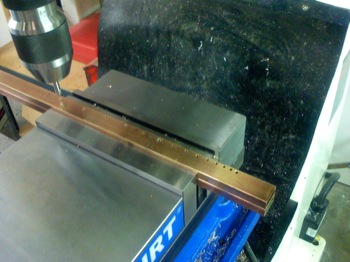
Finished holes for the dipole elements - 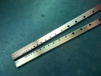
Final raw materials ready for final assembly - 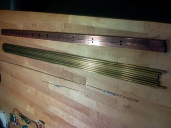
Assembly starting at the high frequency end - 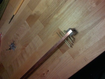
Finished antenna - 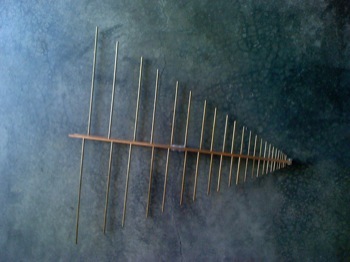
Still need to add mounting sections and the coax/N-connector.
Here's a modified Excel spreadsheet we used for developing some of the basic parameters: LOGPERIO_1.xls.zip
Posted by: Lab Coat
| @ May 17, 2012 11:28:27 AM CDT ( ) |
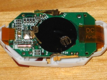
I found this "watch" / remote control while on a Christmas shopping trip to Chicago. I had previously seen various accounts of this device around the internet (including the FCC testing report), but hadn't seen one in person. The "shell" of the product is pretty well done ... perhaps the clasp could've used a little more engineering - however, the guts were pretty straight forward. 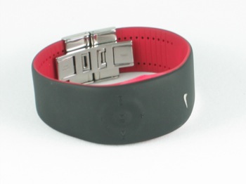
Here are a few views of the teardown:
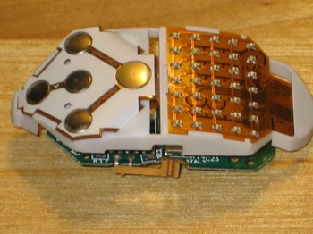
This is of the top outward-looking face. Note the array of LED's of the display; if you did "charlieplexing", it would only take 7 I/O lines to drive the 35 LED's in this array (# = N(N-1) I/O's). They do not appear to do that, using instead 12 I/O lines in a standard Row/Column drive:
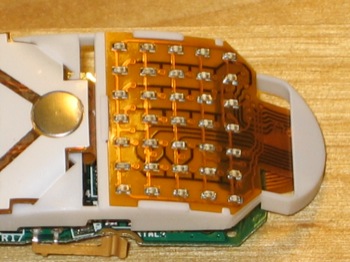
Here's a slightly closer view of the LED array:
Back side (battery) view:
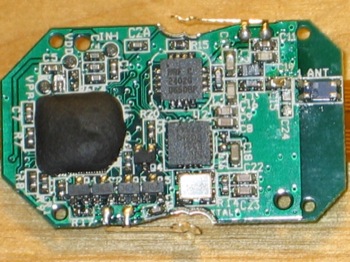
Heart of the matter ... Top IC is an nRF2402 (same as what's used in the Nike+iPod footpod emped) with its associated "blue" chip antenna on the far right. The bottom IC is an 'F331 microcontroller from Silicon Labs. The black epoxy blob on the left is a clock asic. Buttons (there is one on each side, and five on the face) appear to go to the microcontroller.
I've captured some data from the various pieces (footpod, iPod transceiver, and the watch) that I'll post at a later date.
Posted by: Lab Coat
| @ March 19, 2008 1:23:51 PM CDT ( ) |
Interesting that this was (is) the first (readily) available iPhone - compliant (WWi approved) backup battery. Again with the blurry! Damn. 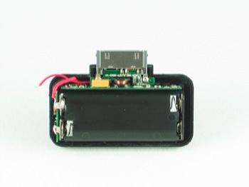
This is pretty standard stuff ... 3v to 5v boost. Not sure of the overall efficiency, but it does work down to about 0.5v. That would be a far stretch, as 2 AAA batteries would be considered dead at about 1.8v. Battery life would depend greatly on the state of the iPhone, but 1-2 hours of talk time is reasonable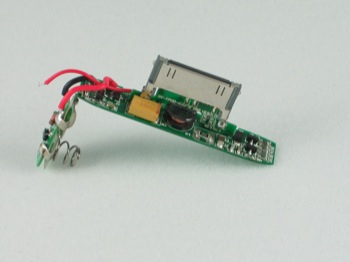
Posted by: Lab Coat
| @ April 1, 2008 1:45:48 PM CDT ( ) |
I wanted to see if Apple did anything interesting (read different) from an EMC perspective in the iPhone sync/charge cable versus the established iPod cable. Aside from the missing hard release latches, and the overall reduced size, there isn't much difference.
Here are some teardown pics on the internals. First one is of the "front" side: 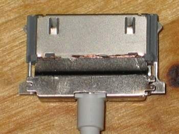
Back side (sorry about the blurry pic): 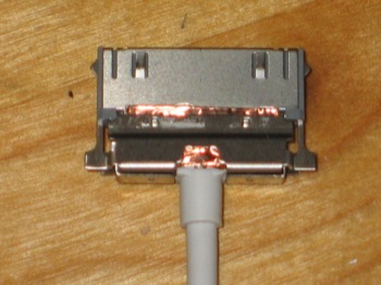
Front side with the metal shield removed ... sorry, but I was too lazy to remove the silicone goo: 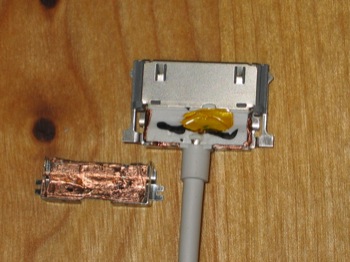
Close up of the "newer" friction latch detail. This style (friction versus hard lock) first appeared on the Apple radio remote product: 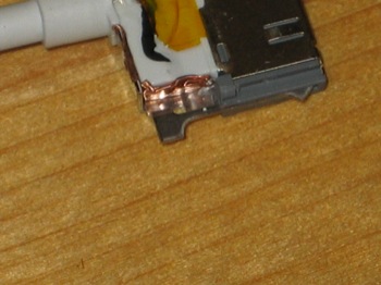
Posted by: Lab Coat
| @ April 1, 2008 1:34:18 PM CDT ( ) |
Previous 5 6 7 8 9 Next
|
|